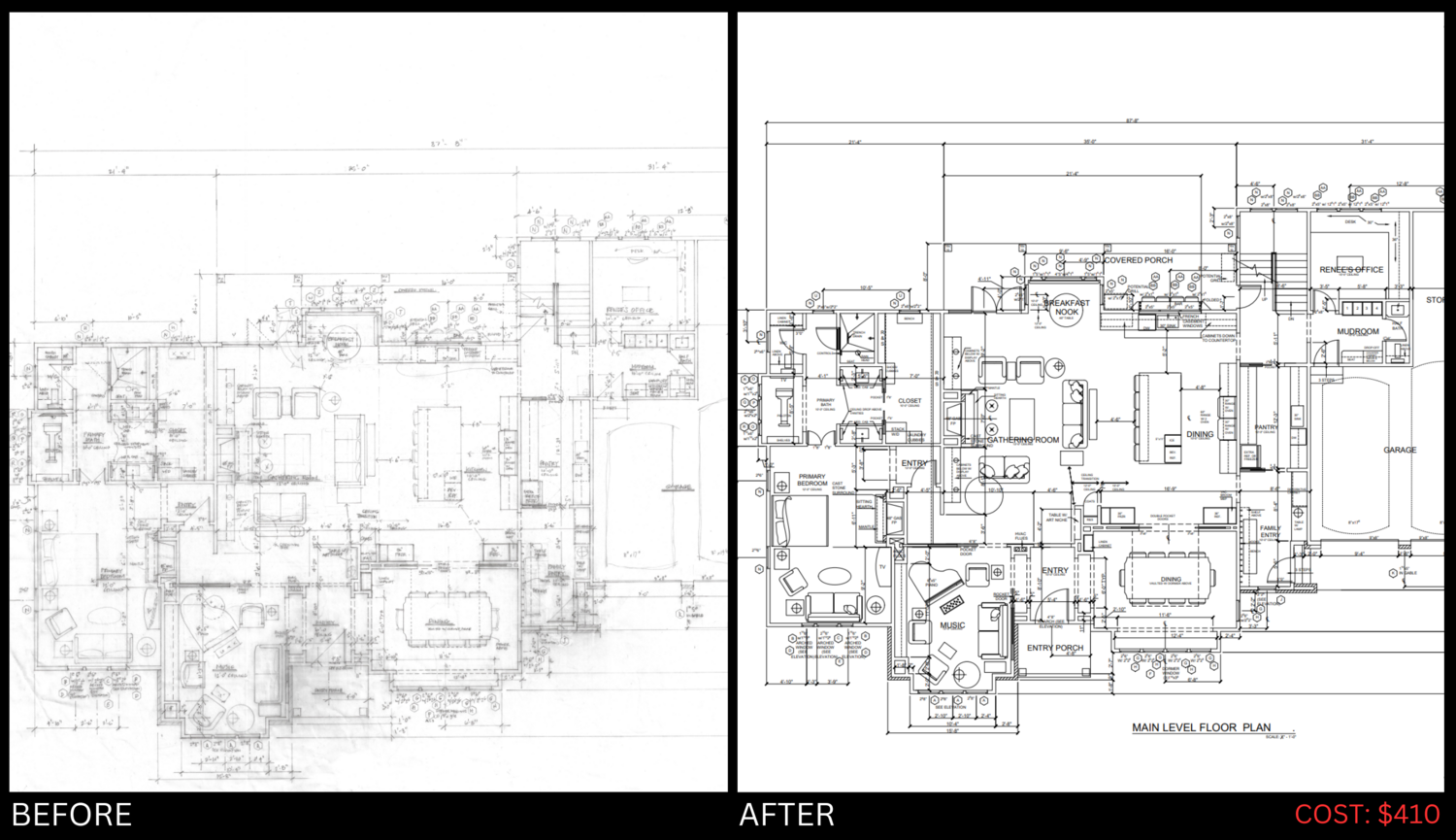
Hand-Drawn & PDF Files To CAD Files (DWG)
Hand-Drawn & PDF Files To CAD Files (DWG)
CADBLOK transforms your hand drawn sketches and PDF designs into precise and editable CAD files. Our expert team ensures accuracy and attention to detail.
- Simple pricing: $0.24 per square foot
- Guaranteed delivery within 3 business days or less
When calculating your total service cost is simple. Just multiply the total square feet you're converting by $0.24.
To make it even easier, add the total square foot quantity to your cart, and it will automatically provide you with the total cost.
Don't worry if you're unsure about the details, after placing your order, one of our designated project managers will reach out to you via phone or email to confirm your order, ensuring all details are accurate before we start the conversion process. Your satisfaction and a fast checkout experience are our top priorities at CADBLOK.
A floor plan is a two-dimensional representation of a building's layout from a top-down perspective. It provides a detailed view of the arrangement of rooms, spaces, walls, doors, windows, and other architectural features on a single level of the building. Floor plans are essential tools for architects, designers, builders, and homeowners, as they convey how the spaces within a building are organized and connected. Here's an overview of the key elements and information found in a floor plan:
1. Rooms and Spaces: Rooms and spaces are outlined with walls on the floor plan, showing their shapes and dimensions. Each room is labeled to indicate its function, such as living room, bedroom, kitchen, bathroom, etc.
2. Walls: Walls are represented as solid lines, and their thickness is often denoted. They define the boundaries of rooms and spaces, creating separation between different functional areas.
3. Doors and Windows: Doors are represented by lines with arcs indicating the swing direction, and windows are usually depicted as small rectangles with or without glazing details. These elements show access points and sources of natural light.
4. Dimensions: Floor plans include dimensions that indicate the length and width of rooms, as well as the distances between walls and various architectural features. These dimensions are crucial for accurately understanding the layout and ensuring that spaces are functional and appropriately sized.
5. Labels and Annotations: Labels and annotations provide additional information about specific features, such as appliances in a kitchen, fixtures in a bathroom, or built-in furniture. They clarify the purpose and function of different elements within each room.
6. Symbols and Notations: Various symbols and notations may be used to represent features like electrical outlets, light fixtures, plumbing fixtures, and other utilities. These symbols help communicate the location and type of these elements.
7. North Arrow and Scale: A north arrow indicates the orientation of the floor plan, showing the direction of north. A scale bar helps determine real-world distances on the floor plan.
8. Furniture and Fixtures: While not always included in architectural floor plans, furniture and fixtures can be added to provide a sense of how the space will be used and arranged. This can be particularly helpful for interior designers and homeowners.
9. Structural Features: Structural elements like columns, beams, and load-bearing walls might also be shown on the floor plan, giving an insight into the building's structural layout.
.png)
